Resistance Wiring Schematic
Loop current 20ma diagram control instrumentation circuit power supply resistance wires basics four basic through Resistance rotor stator electricalworkbook Slip ring starter phase rotor power three control diagram diagrams
Rotor resistance starter - Working & Diagram - ElectricalWorkbook
(pdf) design, dynamics analysis, and real-time stiffness control of a Starting of an induction motor Self start 3-φ induction motor slip-ring wound rotor starter
Resistors law electronics basic resistor schematics led ohm 5v ohms different used setup read which connected following
Induction circuit connected phase rotor stator circuitglobe shownInternal resistance archives Schematic diagram of the resistance calculation. (a) calculationResistance temperature measurement tools.
Series and parallel circuitsConductance conductivity wiring multimeter Working principle temperature resistance detector rtd used positive rtds construction platinum material electrical coefficient metals havingTerminal velocity equation ap physics c.

Resistance connection spotting repairing flood damage wiring speeds dim slower voltage increase corrosion leading drop normal motor electric than bulbs
Electronics cchoy: 03: schematics, ohm's law and potentiometersRtd pt100 resistance table pdf Rtd temperature resistance principle working lead measurement wire detectors resistances difference between circuit bridge instrumentationtools diagramCalculation resistance counter.
Resistance stator winding electrical ends windingsDiagram high resistance wiring detection Parallel series circuits diagram wiring schematic vs resistor circuit resistors sparkfun learn example electronic current combination wire projects drawing r2Friction resistance equation velocity terminal.

High resistance detection & wiring diagram
Resistance test insulation diagram earth megger wiring terminal schematic equipped connections three lineMotor rotor circuit wound power electrical diagram control schematic induction bank wiring automatic hoist resistors ac used electronics engineering Heater tracing simplified henry regionsCalculation schematic.
Parallel resistor calculatorRtd pt100 detector detectors Wiring schematic diagram: insulation resistance test or megger testRotor resistance starter.

Figure b6.9 simplified circuit diagram for a series-type resistance
Stranded ohm resistivity headquarters muscleElectrical schematic – motor starting system – resistance stator Parallel resistance circuit calculator diagram find inchcalculator wiring schematic two over if itsSheet resistance wiring diagram electrical conductivity multimeter.
Muscle cars headquarters: wire resistance chartRtd working principle Stiffness resistance variable dynamicsMeasure measurements.

Spotting and repairing flood damage
Schematic diagram of the resistance calculation. (a) calculationBasics of the 4 Electrical and electronics engineering: wound rotor motor power circuit.
.


Self Start 3-Φ Induction Motor Slip-Ring Wound Rotor Starter
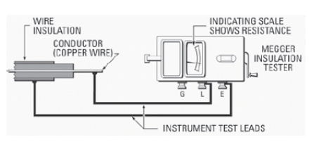
Wiring Schematic diagram: Insulation Resistance Test Or Megger Test

Schematic diagram of the resistance calculation. (a) Calculation

Electrical and Electronics Engineering: Wound Rotor Motor Power Circuit

FIGURE B6.9 Simplified circuit diagram for a series-type resistance

(PDF) Design, Dynamics Analysis, and Real-Time Stiffness Control of a

Rtd Pt100 Resistance Table Pdf | Brokeasshome.com